Treatlife Dual Indoor Dimmable Smart Plug (DP-20) ESP Transplant
Treatlife Dual Indoor Dimmable Smart Plug (DP-20) ESP Transplant

https://github.com/Tediore
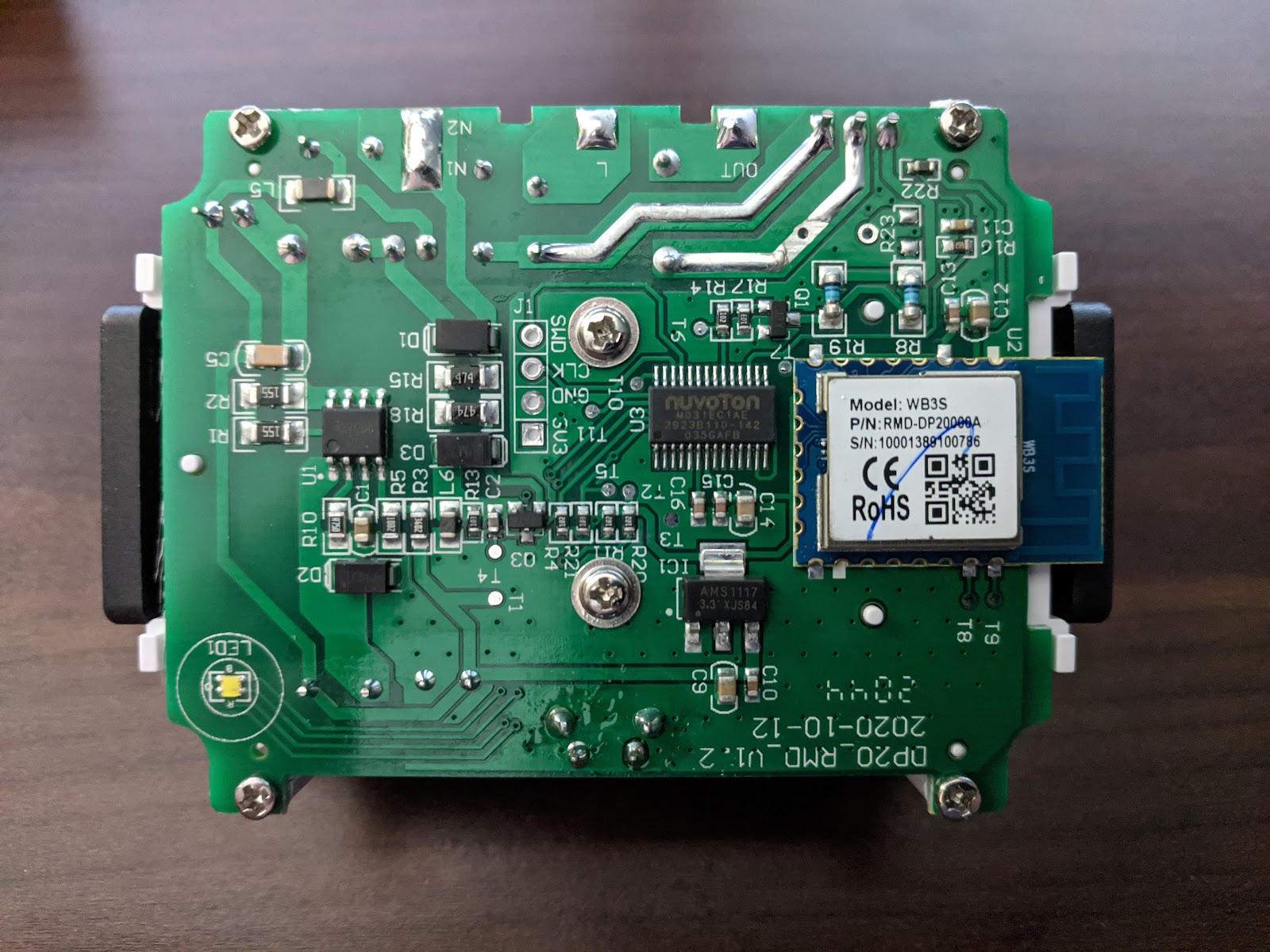
Treatlife released an indoor dual outlet dimmable smart plug in Q4 2020. It ships with a WB3S module which is not compatible with Tasmota but is pin-compatible with the ESP-12 (see the end of this document for a pinout comparison). This means the WB3S can be removed and replaced with an ESP-12 flashed with Tasmota.
Unfortunately the plug is equipped with a secondary TuyaMCU (Nuvoton M031EC1AE, pictured to the left of the WB3S). This means the plug will use the Tasmota TuyaMCU module (Module 54) once the WB3S is replaced with an ESP.

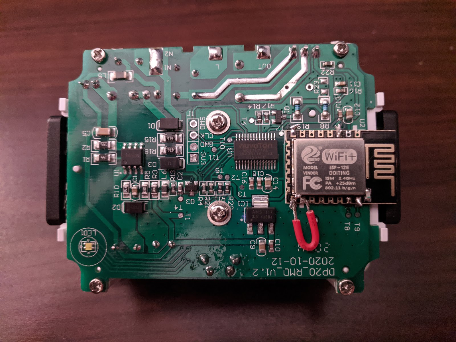
Picture of the final product with an ESP-12 in place of the WB3S. Note the red wire connecting GPIO15 to GND on the ESP. Without this connection the ESP will not boot to normal mode since there’s no pad on the PCB for GPIO15.
A Tasmota Template is not necessary, use the commands below on the Tasmota console.
The commands required to make the device work properly with Tasmota are similar to Treatlife’s DP-10 outdoor dimmer plug:
Depending on the light bulbs you use with this device, you might need to modify the DimmerRange command with a different low value. Both outlets are controlled at the same time (no independent control), and the lights gradually fade when turned on or off. Unfortunately it does not fade between brightness levels.
Pinout comparison (WB3S on the left, ESP-12 on the right):

Submitted by M.J. Wydra
https://github.com/Tediore
I purchased Treatlife's fan only controller and have removed the WB3S and replaced it with a ESP-12S last night. I have not tested it yet, but I am curious as to why you had to connect the red wire from GPIO15 to GND. On mine there was a pad there. Did the pad get ripped up when you removed the WB3S?
ReplyDeleteThanks!
There was no actual pad for IO15, there was just a rectangle that was the size of a pad (you can see that in the third photo)
DeleteDoes the Treatlife fan only switch work with the chip replacement like this?
DeleteYup. I had pics of it and talked about it in this one https://youtu.be/hskofG2eiGs
DeleteDoes it matter which ESP-12 you use. E, F?
ReplyDeleteThe F supposedly has a little better WiFi antenna.
DeleteProgramming this ESP-12 looks to be lot more complicated. Did you program it after attaching it to the dimmer or before?
DeleteI have one of these. Makes it really simple to program before you install it. https://amzn.to/3b2oNzg
DeleteThis comment has been removed by the author.
DeleteI modded a fan controller with the 12F and it worked great. 1. flash ESP 12F with Tasmota, 2. heatgun / flood soldier old chip off board, 3. flux and clean, 4. heat gun / solder new chip on board, 5. test and reassemble. Once wired in you will end up with Tasmota - XXXXXXX on your wifi, just program as usual.
DeleteThanks for the project and learning experience it worked. Always wanted to tinker with doing some chip surgery like this and it worked. Here are the items I bought. The rework station isn't necessary but might save ripping off some pads. So now I have two good soldering stations. The programmer may also not be needed but I couldn't get it programmed without. Programming with with the programmer adapter was very easy.
ReplyDeleteESP-12 Chips
https://smile.amazon.com/gp/product/B07SDMHYY8/ref=ppx_yo_dt_b_asin_title_o04_s00?ie=UTF8&psc=1
Treatlife Dimmer Plug
https://smile.amazon.com/gp/product/B08LPYXK6L/ref=ppx_yo_dt_b_search_asin_title?ie=UTF8&psc=1
Programmer
https://smile.amazon.com/gp/product/B08BXMGVNM/ref=ppx_yo_dt_b_asin_title_o02_s00?ie=UTF8&psc=1
Soldering Iron Hot Air Rework Station
https://smile.amazon.com/gp/product/B07RY5XWVG/ref=ppx_yo_dt_b_asin_title_o03_s00?ie=UTF8&psc=1
Thanks for the info. I was able to convert my Treatlife dual dimmer and also a ST10 (LED strip light). I am planning on trying the LED Night Table Lamp too. This makes those products even better.
ReplyDeleteI am considering doing a chip transplant for the my treatlife smart dimmer switches as they require unseating pins on the secondary MCU and I think it would be easier to simply remove the ESP chip, reprogramming it and reseat it.