Can we flash Tasmota on it? YES!
But can we flash ESPHome on it instead? YES! (Thanks to zeroping!)
The Linkind Smart Switch is rather unique. It uses an ESP32 chipset with Bluetooth support, two independent buttons, two independent LEDs (behind the small hole) of green/red and one relay. It ships with a non branded white screwless decora faceplate. The switch can also be used in multi-gang boxes as they have the additional mounting holes.
Bought the dimmer? The instructions for flashing/disassembly will be the same except when you get to the software to push over to the dimmer itself. Software will be linked down below for the dimmer in the steps.
(Click any of the photos for a larger view)
Relay ratings
To open the switch, there 4 small torx screws in the face. I used the one out of the iFixIt kit but a small flat head screwdriver could also be used. Remove the four screws on the face and pull it straight up. There will be some tension as 8 header pins intersect the faceplate board.
Take note, the switch will not power up unless the air gap switch (reddish switch on the right) is depressed by the faceplate air gap insert (safety feature)
Pop the board out with a spudger or flat head screwdriver and flip it over.
Look for the row of pads that have VCC1, GND, etc.
You can choose to either bend some clips or solder to the pads. Remember to connect RX to TX and TX to RX on your USB TTL flasher. The pads are as follows from Left to Right; RX, TX, GPIO Zero, skip RST, Ground, and 3.3 volts. DO NOT apply 5V to this pad, the magic smoke might come out. GPIO Zero will also need to be connected to ground either for the first few seconds while power is applied or the entire flashing time.
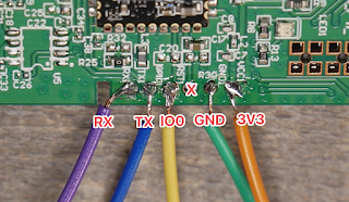 |
| Solder method |
 |
| Bent clip method (credit: @tony on digiblurDIY Discord) |
I use a USB cable with an
inline power switch to make flashing easier but it isn't required. The ESP32 on this switch requires the
Tasmota32 Solo1 version bin file. You can flash this version straight from your browser by going to
https://tasmota.github.io/install/
If you bought the dimmer, go ahead and follow through the same steps. There is an additional file to push to the switch as the last step.
Select Tasmota32 Solo1, check reset defaults and click install. If you want Bluetooth scanning too, scroll all the way down and choose "Tasmota32 Solo1 Thermostat + BLE".
NOTE: It has been found due to the ESP32, power requirements are higher and some
USB TTL adapters may not be able to power the device properly and may fail during the flash and/or the WiFi setup of the device. I was able to flash and power the switch with this adapter
CP2102 USB TTL
Once it is complete you can remove any wires, reassemble the switch and power the device via mains AC power.
Add the device to your network via the AP mode (ex: tasmota_XXXX) - Browse to 192.168.4.1, pick your WiFi network and enter your WiFi password.
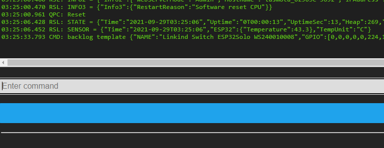
Browse to the Device IP address. Click Consoles then Console (sometimes the Tasmota ESP32 webserver can be laggy and refresh or multiple clicks is required)
Paste in the following command all on one line and hit enter (if you bought the dimmer skip to the dimmer subsection below).
backlog template {"NAME":"Linkind Switch ESP32Solo WS240010008","GPIO":[0,0,0,0,0,224,1,1,0,0,288,0,1,1,0,0,0,0,0,0,0,576,321,0,0,0,0,0,33,32,0,0,0,0,0,0],"FLAG":0,"BASE":1} ; Delay 1 ; Module 0
The switch should reboot and if you return to the main menu it should show the switch name and the toggle button should be available. You can now add the switch in your home automation platform. If you are using Home Assistant, I highly recommend the Tasmota HA integration method.
Optional: If a Red LED while Off and Green LED while On is desired paste the following rule into the Tasmota console. If you want opposite colors, edit the template in the configure template screen and transpose Led_i with Led and vice versa. The "i" stands for inverted. Copy the below rule as one line to the Tasmota console:
Rule1 on power1#state do backlog ledpower1 %value%; ledpower2 %value% endon
on power1#boot do backlog ledpower1 %value%; ledpower2 %value% endon
Activate the Rule with
Rule1 1
The ESP32 Solo supports Bluetooth scanning too with the correct bin file. Currently use the Tasmota32 Solo1 Thermostat + BLE file. Bluetooth was tested by a couple of us including myself extensively, it seems to work well even being a single core ESP32. Check out the
Tasmota Blerry Project.
NOTE as of 1/4/2022 the Thermostat + BLE bin file has a bug with the PowerOnState. It will always cycle the relay off when the device is rebooted via power or via software. The normal Solo bin without BLE support does not have this issue, you can also compile your own bin without thermostat to correct this bug.
 |
| credit: @tony on digiblurDIY Discord |
If you have any questions or get stuck during the process, join us in the Discord chat (link below)
Additional Dimmer Instructions
Currently as of 2021/11/01 pcdiem as graciously provided a precompiled bin file with Bluetooth support and the necessary code to make this dimmer work. This replaces the previous proof of concept solution with the Berry script files. No template, no scripts, etc is required. Go to the following webpage and download the bin file with or without Bluetooth support.
Do I need bluetooth support? If you plan on receiving bluetooth sensor readings such as from these
sensors then yes. If no, then choose no bluetooth support bin, you can always upgrade the software via the web GUI of Tasmota later if necessary.
Navigate to the Web GUI of the Linkind dimmer. Choose Firmware Upgrade. Select Browse. Choose the bin file downloaded from the link above. It should reboot after a few minutes and return to the main menu of Tasmota.
Choose Configuration then Configure Module
Select the Linkind, then hit Save.
The dimmer is now ready to be added to your home automation software such as Home Assistant. If necessary you may need to change the
dimmerrange value on the Tasmota console to fit your scale of dimming on the bulbs you have connected.
Linkind WS240010008
Linkind WS240010108


Take note of the max 500W rating. I prefer the Gosund 4 pack for a little more money for the full 1600W equivalent.
ReplyDeleteSorry 600W incandescent/300W CFL. I do like the dual button setup. Don't really understand the need for the air gap piece.
DeleteI see that on a lot of Zwave/Zigbee switches as well.
DeleteWhile true it has a max rating (LED) of 300W, I will be powering a 20W LED with it and the extra button for automations is bonus.
ReplyDeleterickr
Indeed. I've got a 22,000 lumens floodlight that blind you and it pulls 160w. I am curious of this 300W LED project.
DeleteVery nice. Have you tried the dimmer version? Would it be the same process?
ReplyDeleteI just did the dimmer and is the same process but I don't know what are the settings for have it works as dimmer!!
Deletecheck the discord, we've been working on them and have working proof of concepts going as it uses i2c communcations. But we did get it working.
DeleteI'm attempting to get the dimmer working under ESPHome. Still trying to understand what the heck this dimmer IC is - I2C? PWM? Either one? Why did they need to offload all of this to that second ARM chip, rather than doing it all with the ESP32?
DeleteI see https://github.com/pcdiem/Tasmota/commit/4afbe059538c38f68f60ad8745935365e51b08f0, but it looks like that code uses PWM.
Any pointers would be helpful.
We all questioned that as well as we went through the reverse engineering as well. Just seems weird but I do get it in some ways as it allows them to change the wifi module out easily and have a secondary MCU do all the coding work.
DeleteDoes that bent clip trick work with the Sonoff switches?
ReplyDeleteAlso, I ordered these using you link. I'm loving your channel
Thanks! Which sonoff switches?
DeleteHi, great content as always! I was wondering if Tasmota will let you turn on or off the LEDs to disable them or even use them in automations based on the color of the LED green/red/orange?
ReplyDeleteYes, the LEDs are controllable however you want to use them.
DeleteI am bought all the pieces for this directly from the links. I am trying to figure out where GPIO 0 gets connected on the TTL USB flasher?
ReplyDeleteWe got you going on the discord chat I believe?
DeleteYup! Got it all flashed! Discord is excellent
Deletecan you link that discussion I am trying to flash mine and can't figure it out also
DeleteIt won't let me link that thread under the hotdeals section on my discord, it's labelled Linkind dimmer
DeleteI am using linkind dimmer (flashed with tasmota32solo1-linkind-ble.bin) with NON dimming Ecosmart bulb. I expected it to turn off completely when toggled to OFF but it does NOT (it is on with very small brightness). Is this correct behavior?
ReplyDeleteWith dimming Bulb, it works perfectly (ON turns on with last dimmer value, OFF turns of the bulb).
Bavant Patel
I would expect weird things with non-dimmable bulbs in a dimmer.
DeleteWould the dimmer switches work with controlling a ceiling fan?
ReplyDeleteNot directly. You'd need a fan controller that would do the capacitor switching like an iFan04.
DeleteCan the LED colors be changed?
ReplyDeleteThere are two LEDs. Red and Green, you can set to do whatever you want as they are on their own GPIO pins.
DeleteThanks for testing the sole1 ble file and confirming the issue I am having. Watching you videos on compiling Tasmota. Trying to figure out how to make a solo1 with ble. The tasmota directions say start from scratch. How do I figure out what is in the current build?
ReplyDeleteSpent the day today flashing two of these switches (no dimmer). I am very comfortable flashing Tasmota as I have over a dozen ESP8266 devices in my home, all connected to Home Assistant.
ReplyDeleteStarted reading the blog and realized these are EPS32 devices. A slightly different animal to deal with.
Problem #1 - the bent clip method just did not work for me because the pins/solder pads for Rx, Tx, GPIO0, GND, and VCC are just a fraction too far away from the edge of the board. So, I soldered.
Problem #2 - My soldering iron is garbage. Enough said.
Problem #3 - the web-based installation tool does not work on Linux Mint, possible any Linux distribution, but I'm speculating on that point. 1 hour wasted until I decided to switch over to Windows, which worked the first time.
Problem #4 - The location of the ground screw causes the switch to interfere with the electrical box mounting screw. Seriously!? I'd like to have a few words with the engineer responsible for that decision. I had to shift my switches (both in a double-gang box) about 2 mm to the right. The switch on the right was up against the right inner wall of the electrical box. This seems like a big design issue to me. Yes, I managed to get both switches in the box after shortening wires and changing out wire nuts for Wago connectors. The Wago's saved me.
After all is said and done, the switches are in and working and connected to Home Assistant, which was a breeze (automatic with Tasmota).
The bent clip / sodering issues were all mine. Nobody else to point a finger at here.
The installation tool (Linux/Windows) issue... well, now I know.
The ground screw issue... deal breaker for me. I will not buy anymore of this switch.
The ground screw sticking up is indeed an issue for some boxes, I'd suggest another grounding method are a small spade to get on this wire.
DeleteDid you decouple the buttons or something or have some rules? By default both buttons should toggle the relay from what I remember. I have changed mine since I'm using it in a device group with smart bulbs. Jump into discord and lets test a few things to get you going if you can't figure it out.
ReplyDeleteHey digiblurDIY, have you looked into the second generation for these switches? Is this process still applicable or did they replace the chip for something incompatible with Tasmota?
ReplyDeleteThey cheapened the switch out big time and also removed the ESP. Do not buy the 2nd gen models.
DeleteTravis, Once again a thank you. I flashed two of the regular Linkind switches today. The first was just like your instructions, I used the web flasher, the bent pin hooks and all went well. The second just would not flash, I tried using the web flasher and the esp tool. I suspected that is was having power issues, so after seeing your discord post, hooked up a DC power supply. After lots of attempts it finally flashed, but then it would not broadcast the tasmota ap. I eventually used termite to communicate with it and set up the wifi using backlog commands. I got it done, but the ROI on my time was pretty poor, those preflashed Tasmota switches are looking cheaper everyday. That being said, without your great tutorials I would have never got it done. Thank you.
ReplyDeleteNice job!!!
Delete